CPSC 543 Project - Second Iteration
In this iteration, We use ideas about possible shapes and size of the joystick interface from previous iteration. Circular egocentric view around the wheelchair joystick can be realized using combination of visual percept and tactile sub-addition. We describe the exploratory technology implementation phase of our physical user interface design project in the following section.Egocentric View
Powered wheelchairs are usually driven by joystick interface modified as per users needs. Our user study from previous iteration suggests that users prefer joystick that has larger surface area as it provides more sense of control and comfort. We use this opportunity to design an embedded navigation assistive physical user interface that would fit into the joysticks on these wheelchairs. We use egocentric view representation on a dome shaped physical interface as a visual sense of collision free direction. This visual guidance is supported by haptic rendering as a sub-additive sensory modal to stimulate user reaction. Similar work has been done in [1], where they use haptic display to block motion of joystick in certain direction, LED display around the joystick knob to indicate direction free from obstacles and an audio prompt to prompt user towards certain direction. Auditory percept requires user to process and execute the percept. It would be useful to provide a natural guidance that would direct the user towards a suitable trajectory. Here we extend to using shear force and vibratory haptic guidance instead of audio prompts with the hypothesis that it can provide a sense of natural guidance towards a safely projected trajectory.Visual Display
We use a RGB LED ring comprising of 24 serially controllable red, green and blue channels. We found this display suitable (see Fig [1]) for the size of the user interface we are considering to build.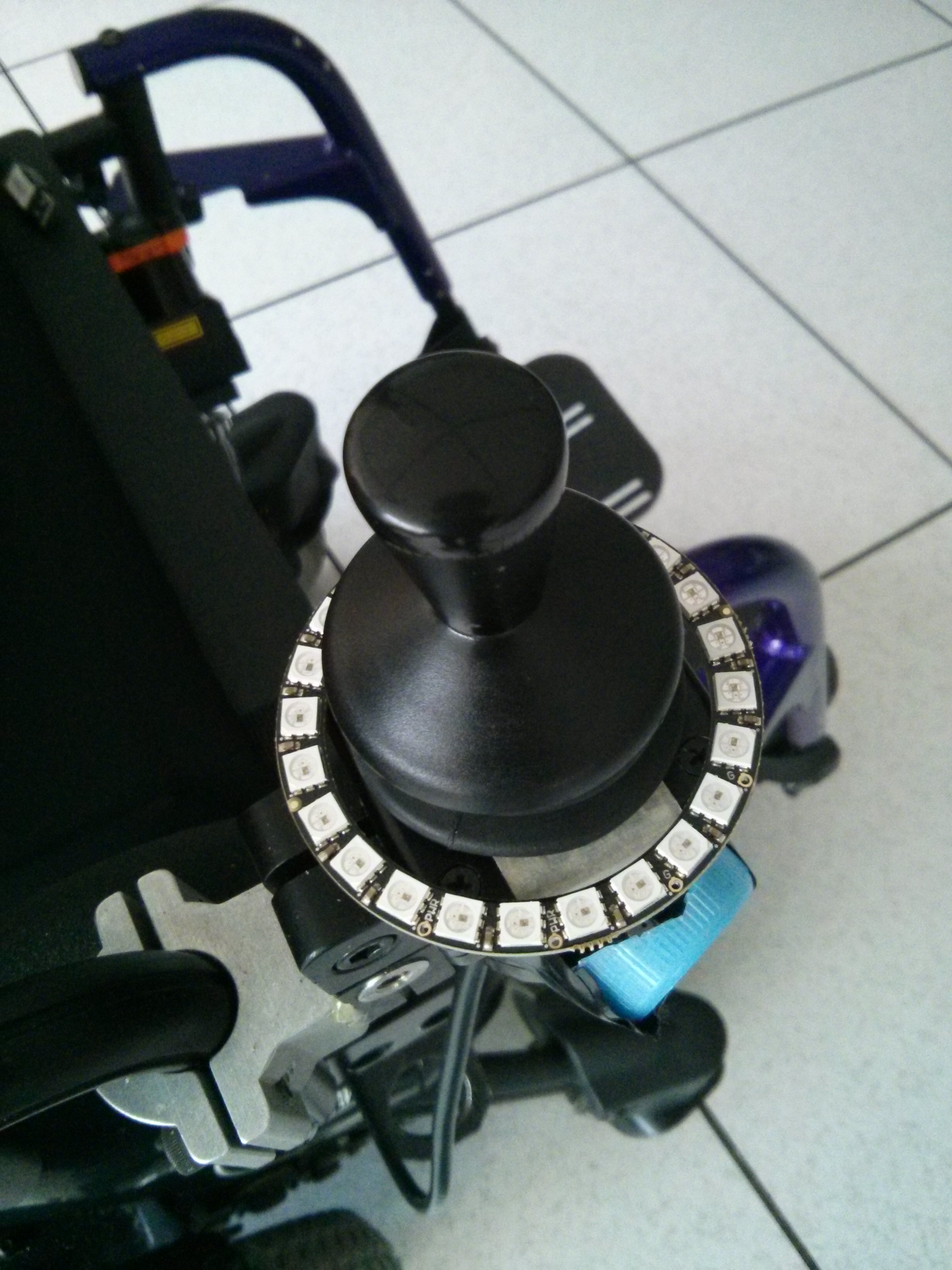 Figure [1] Egocentric LED display around wheelchair joystick
Our first attempt was to use egocentric LED display to point in the direction towards the which the intelligent system wants to guide. Figure [2] shows the brightest green as the direction of possible heading.
Figure [1] Egocentric LED display around wheelchair joystick
Our first attempt was to use egocentric LED display to point in the direction towards the which the intelligent system wants to guide. Figure [2] shows the brightest green as the direction of possible heading.
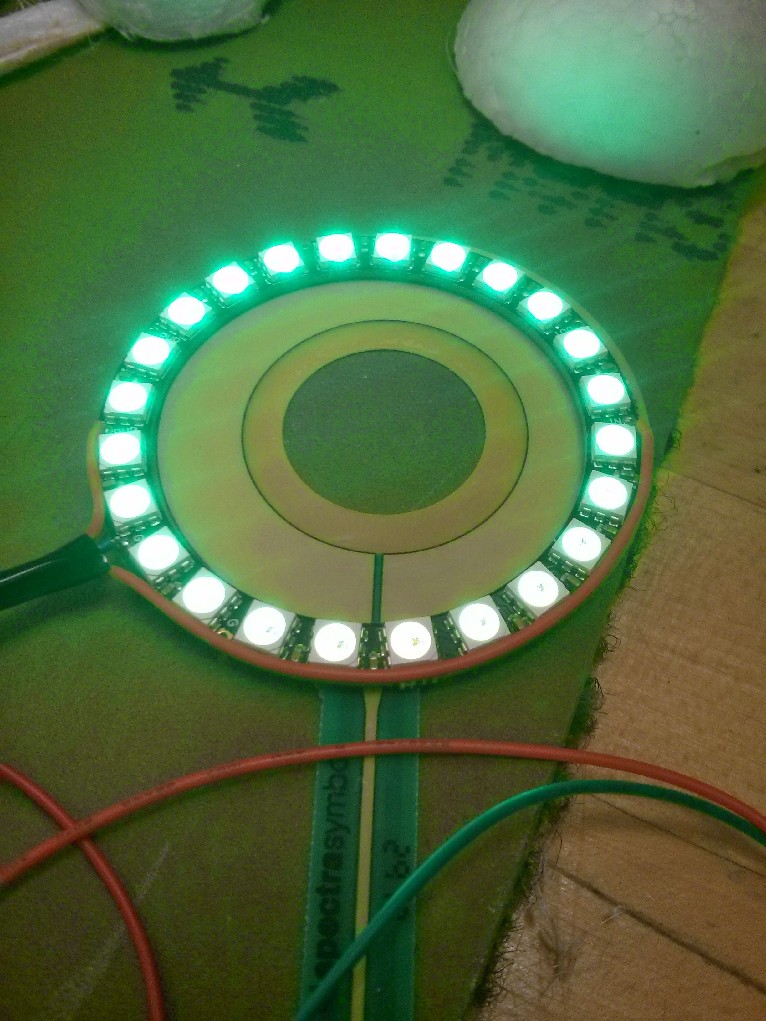 Figure [2] LED display showing green head in the direction away from obstacle
Another form of display would be suggestive of direction towards which the joystick could turn. We simulated this using trailing LEDs. This video
Figure [2] LED display showing green head in the direction away from obstacle
Another form of display would be suggestive of direction towards which the joystick could turn. We simulated this using trailing LEDs. This videoHaptic Rendering
We use a similar approach to haptic rendering as to that of visual display. We use a servo motor with an arrow like shaft on top to point in the direction of guidance. We mounted this motor into a hemispherical surface in such a way that the palm surface would be in contact with the pointer. This videoEgocentric Input
As input, we also calibrated the circular potentiometer against LED display. This feature can be used to control the pan-tilt unit on which the camera of the wheelchair is mounted. In this video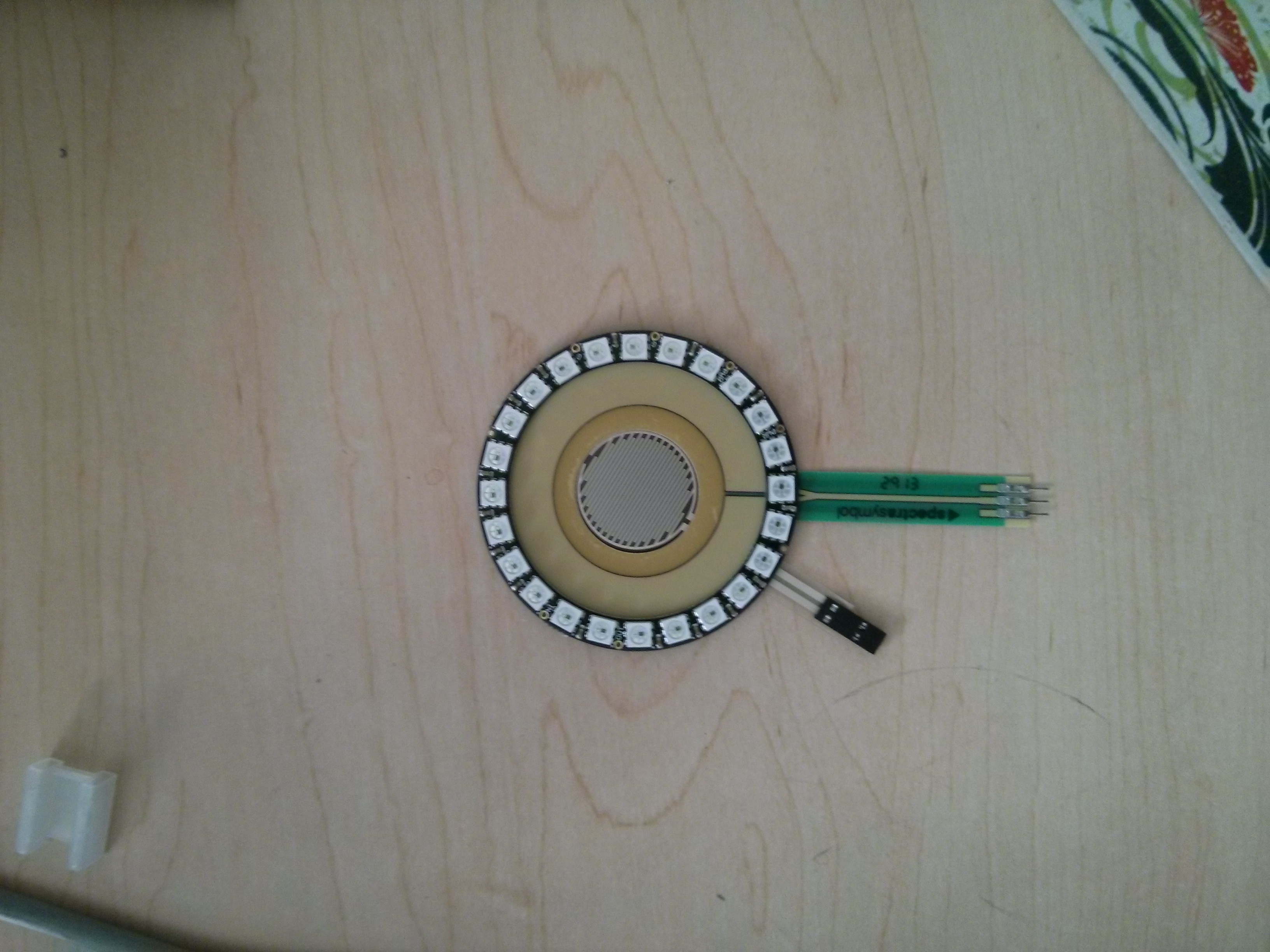 Figure [3]: Touch sensors (circular and point pressure type touch sensors)used in this project
Reflections
In this iteration, we focused on generating basic visual and tactile patterns showing target position and target heading. We used egocentric approach to representing the environment around the wheelchair. We demonstrated some of the patterns using a servo motor, a vibration motor and circular LED display. We achieved position and direction guidance like behaviour using LED display. Using a vibration motor was challenging to control and localize vibration. Our simple experiment showed some promise on displaying direction guidance using vibration feedback. We experimented with some simple shear force mechanisms to observe, if we can realize position and direction guidance. Our eccentric wheel based shear force display appears to be able to render both position and direction. We will explore this domain in our next iteration. The input section experimented in this iteration is merely an illustration of a working sensory system. We intend to use this sensory input to control the pan-tilt of the wheelchair camera so that the user can obtain vision based system's assistance. Right now, we have only used the circular touch sensor. This sensor could be used to turn the camera around by mapping sensor to the camera position (similar to mapping LED display with sensor position). We intend to incorporate controllability of tilt as well using combination of circular and point touch sensor with gestures such as swiping up and down to tilt the camera up and down.Next Iteration
In next iteration, we plan to refine the haptic displays using shear force. We will integrate visual and haptic displays together into a single system. If time schedule aligns with my user interview, I will conduct a final interview with the user to get feedback on the designed interface. We also plan to integrate pan-tilt control using the touch interface. Reference: [1] Wang, R. H., Mihailidis, A., Dutta, T. and Fernie, G. R. (2011). Usability testing of multimodal feedback interface and simulated collision-avoidance power wheelchair for long-term-care home residents with cognitive impairments. Journal of Rehabilitation Research and Development, 48(6), 801-22. doi:10.1682/JRRD.2010.08.0147 -- BikramAdhikari - 24 Mar 2014

| I | Attachment | History | Action | Size | Date | Who | Comment |
|---|---|---|---|---|---|---|---|
| |
Sensors.jpg | r1 | manage | 1869.7 K | 2014-03-24 - 14:42 | BikramAdhikari | |
| |
display_position.jpg | r1 | manage | 1485.5 K | 2014-03-24 - 14:44 | BikramAdhikari | |
| |
joystick_wheelchair.jpg | r1 | manage | 1994.5 K | 2014-03-24 - 14:43 | BikramAdhikari |
Topic revision: r2 - 2014-03-24 - BikramAdhikari

Ideas, requests, problems regarding TWiki? Send feedback