Lab 5: Lets Make Something Engaging
In this lab, we used with the Pong software to experience haptic rendering using the twiddler. We also experimented with our own implementation of a controller that generated an output signal to the motor based on sensor readings from the encoder mounted on the rear shaft of twiddler's motor. Finally, we developed a model of a robot steering system and rendered its steering motion on the twiddler. Following sections describe them in details.Motor Controller Implementation
We had to replace myPID.Compute() function with our own implementation. In the main loop of the program we replaced this function call with the following code snippet. 1. long pid_t = millis(); 2. long pid_dt = pid_t - pid_last_time; 3. if(pid_dt>=1) // 1ms is the Sampling Time 4. { 5. prev_p_error=p_error; 6. p_error=pos-target; 7. d_error=pos-prev_pos;//p_error-prev_p_error; 8. PWMOut= p*p_error+d*d_error; 9. if (PWMOut>255) PWMOut=255; 10. else if (PWMOut<-255) PWMOut=-255; 11. pid_last_time=pid_t; 12. //SetPWMOut(PWMOut); 13. } In lines 1-2, we track the current time and time difference from previous iteration of the PID loop in lines 3-13. When the time interval exceeded Sampling time of 1ms, we compute proportional and derivative errors in lines 6-7. Our spring mass damper type controller is implemented in line 8. Lines 9-10 assure PWM output to not exceed its extreme values. Initially, we did not have fixed time step. We ran this loop as fast as possible using the same value of p and d terms as originally used by myPID.Compute() expecting it to work. It did not work in the same manner as before. Then, we began tuning the controller and observed that the controller worked similar to myPID if the d term was scaled approximately 1000 times the value used by myPID.Compute(). Expecting the cause to be faster running loop and/or not fixed time, we used fixed times sampling as described in lines 1-3. The result did not change significantly. Still confused about why would the derivative gain have to be so high for the controller to work, we checked the PID library. We found that the derivative term and the integral term we scaled from milliseconds scale to seconds scale in the library. The reason behind that scaling is still not clear to us.Rendering Steering Wheel motion on Twiddler
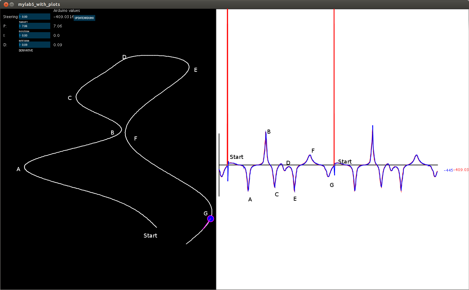 Fig 1. Rendering Steering Wheel Motion on Twiddler video

| I | Attachment | History | Action | Size | Date | Who | Comment |
|---|---|---|---|---|---|---|---|
| |
steering_rendering_labeled.png | r1 | manage | 70.2 K | 2014-03-28 - 14:29 | TWikiGuest |
Topic revision: r1 - 2014-03-28 - TWikiGuest

Ideas, requests, problems regarding TWiki? Send feedback