The execution time of our algorithm was compared to the
execution time of the full algorithm in order to get a measure of
the relative speedup. Both algorithms were provided with a sequence of
images obtained from a mobile robot (Spinoza at Laboratory
for Computational Intelligence
at the University of British Columbia). The robot has two black and white
cameras mounted on it. A sequence of  gray-scale images
was obtained while the robot was moving through the laboratory.
The robot was programmed to translate forward 5cm, capture a set of stereo images,
rotate 3 degrees, and capture another set of stereo images.
The robot repeated this motion twenty times.
gray-scale images
was obtained while the robot was moving through the laboratory.
The robot was programmed to translate forward 5cm, capture a set of stereo images,
rotate 3 degrees, and capture another set of stereo images.
The robot repeated this motion twenty times.
The amount of information about the motion of the robot was
broken down into three types;
myitemizeitem Type A: robot moves  cm and rotates
  Type B: robot moves
  or rotates
  Type C: robot moves
  cm or rotates
Figure 6 presents the information at the beginning of the
sequence. The images shown are the views form the left and right camera.
The disparity maps shown are the result of processing with the full
algorithm. The shades of gray represent the valid disparities. The brighter
shades of gray represent points in the scene that are closer to the viewer.
The black areas of the image represent invalid points.
The image labeled with maximum disparity range
is the upper bound on the the disparity range for all pixels,
given that the robot has rotated to the right
anywhere between 0 and  . The shades of gray represent the
upper bound of the disparity search range and black pixels represent points
that are believed to be invalid. The white areas of the image represent
the lack of information from the previous image. The right part of
the image therefore has a white vertical strip, because the robot had
moved to the right.
. The shades of gray represent the
upper bound of the disparity search range and black pixels represent points
that are believed to be invalid. The white areas of the image represent
the lack of information from the previous image. The right part of
the image therefore has a white vertical strip, because the robot had
moved to the right.
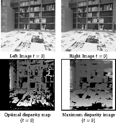
Figure 4: Processing done when the robot turns to the right
Figure 6 displays the last stereo pair of images in the sequence and the results obtained both by the full algorithm as well as the result of the coherent stereo algorithm. The result of the coherent stereo algorithm was obtained given that the general direction of robot motion is known.
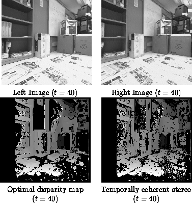
Figure 5: Processing done at the end of the robot motion
The performance of the algorithm is analyzed by a number of criteria presented in Table 6. The speedup is calculated as the ratio of the CPU time used by the full algorithm over the CPU time used by the coherent stereo algorithm. The time spent in computing the disparity ranges is included in the time of the coherent algorithm. The CPU time spent on calibrating images is not considered for either algorithm. The column valid matches represents the percentage of the valid disparities correctly identified by the coherent stereo algorithm. The average error column presents the average difference between the disparity values found by the full algorithm and values found by the coherent algorithm. The error over 1 column presents the percentage of pixels that are different from the correct result by more than 1.
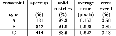
Table 1: Comparison of performance between the full and coherent stereo algorithm