Image ambiguity area is part of the image that a pixel may move to given the constraints on motion of the camera. We are interested in determining the boundaries of this area because it contains the minimum and maximum disparity that the pixel will have in the next iteration of the algorithm.
In Figure 1 we present the pinhole model of one of
the cameras in the stereo camera setup.
The oval represents the lens of the camera.
The  and
and  axis define the camera coordinate system.
The
axis define the camera coordinate system.
The  is on the image plane, the
  points towards the scene.
The curved line at the top of the figure represents the scene
viewed by the camera. The focal length of the lens is labeled with
the letter
points towards the scene.
The curved line at the top of the figure represents the scene
viewed by the camera. The focal length of the lens is labeled with
the letter  . The point
  on the image plane is the projection
of a point
on the image plane is the projection
of a point  in the scene.
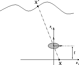
Figure 1: Pinhole model of the camera
For simplicity, we will consider only a two dimensional motion of
the camera. The motion of the camera is parameterized by the
possible translations along the  and
and  axes
axes
 and
and
 ,
and rotation around the pinhole of the camera
by
,
and rotation around the pinhole of the camera
by  .
Figure 2 shows the extreme possible positions of the camera after motion.
The shaded rectangular area represents the possible
positions of the camera relative to the current position of the
camera. The new positions of the camera are chosen
to reach the farthest visible point in the scene given the constraints
on its motion.
.
Figure 2 shows the extreme possible positions of the camera after motion.
The shaded rectangular area represents the possible
positions of the camera relative to the current position of the
camera. The new positions of the camera are chosen
to reach the farthest visible point in the scene given the constraints
on its motion.
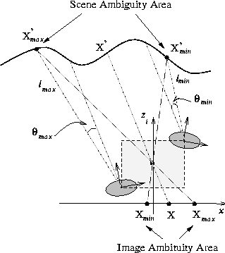
Figure 2: Computing the ambiguity area
We consider the point  in the image. We are interested in calculating
the position of points
in the image. We are interested in calculating
the position of points  and
and  that define the
image ambiguity area. The point
that define the
image ambiguity area. The point  is the projection of a point
 in the scene. After the camera moves, a number of points
in the scene can project back onto point
in the scene. After the camera moves, a number of points
in the scene can project back onto point  . We are interested in
calculating the position of these points in the current image.
This is done by considering the most extreme positions of the camera.
The dotted lines,
. We are interested in
calculating the position of these points in the current image.
This is done by considering the most extreme positions of the camera.
The dotted lines,  and
and  ,
represent the line of sight from point
,
represent the line of sight from point  at the
extreme position of the camera after motion. The intersection of the
dotted lines and the scene are the left most point
at the
extreme position of the camera after motion. The intersection of the
dotted lines and the scene are the left most point  and the
right most point
and the
right most point  that can project onto pixel
  after the motion of the camera.
When the points  and
and  are projected back onto
the image plane we obtain the points
are projected back onto
the image plane we obtain the points  and
and  .
The range between these two points contains the pixel that
point
.
The range between these two points contains the pixel that
point  will see after the camera has moved. Therefore
the ambiguity area is
will see after the camera has moved. Therefore
the ambiguity area is
 and
and 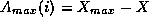 .
.
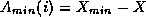
The extreme lines of sight for the point  ,
,  and
and  ,
are a function the robot motion:
,
are a function the robot motion:


 ,
,  and
and  can be easily determined using
simple geometric transformations.
Once the extreme lines of sight are determined, the positions
can be easily determined using
simple geometric transformations.
Once the extreme lines of sight are determined, the positions
 and
and  is a function of the scene structure.
The structure of the scene is defined by the disparity map
is a function of the scene structure.
The structure of the scene is defined by the disparity map  in the one dimensional case considered in this example.
The position of points  and
and  is determined by
searching for the point that either lies on the lines
is determined by
searching for the point that either lies on the lines  ,
,
 or is closer to the image plane.


Where  is a function that determines the location of
the point in the scene, given the disparity and the position of its
projection,
is a function that determines the location of
the point in the scene, given the disparity and the position of its
projection,  and
and  are the coordinates of the
left and right most pixel in the image.
are the coordinates of the
left and right most pixel in the image.
This example considers two dimensions. The derivations are fully applicable in three dimensions and will not be discussed in detail.