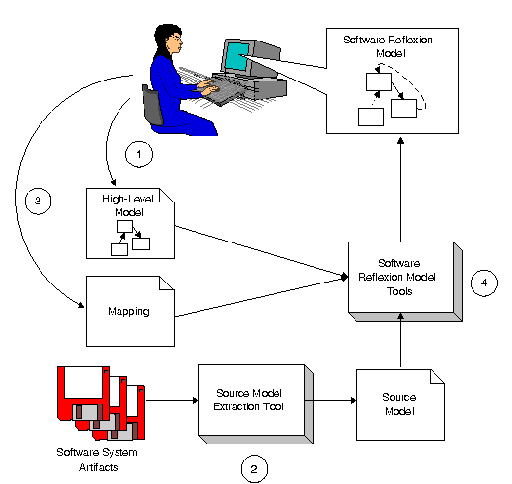
To illustrate the key features of the Software Reflexion Model technique, this page presents a sketch of its use to aid an engineer with a representative change task. The task facing the engineer is to assess the feasibility of reusing the back-end of the GNU gcc compiler with an existing graphical front-end development environment. Before the back-end may be reused, an engineer must first extract the components comprising the back-end from the source for the compiler.
Since the gcc system is comprised of about 297,000 lines
of source code,
it is difficult for an engineer to gain an understanding of
the system's structure directly from the source code. To apply the
Software Reflexion Model technique to aid with this task, the engineer
applies the four basic steps outlined below.

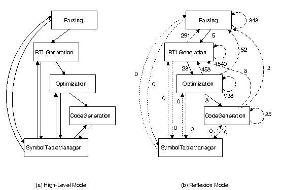
First, the engineer selects a high-level structural model suitable for reasoning about the task. For instance, a high-level model may be a Booch object diagram or it may be a more informal sketch of the calls between modules comprising the system. For the extraction task on the gcc system, the engineer selects the model shown below on the left which is based on a model described by Aho, Sethi and Ullman. This model consists of a set of modules that primarily represent stages of the compiling process and data interactions between those modules. Based on this view, it appears that it may be relatively simple to separate the back-end from the front-end of the compiler; the engineer need only extract the Optimization, CodeGeneration, and SymbolTableManager modules and remove some dependences from the SymbolTableManager module to the Parsing and RTLGeneration modules.
In the second step of the technique, the engineer extracts structural information---called a source model---from the artifacts of the system. For instance, a source model may consist of an inheritance relation between classes in an object-oriented system or a relation describing the message sends between objects or both. A source model may be produced either by statically analyzing the system's source or by collecting information during the system's execution. In this case, the engineer uses a third-party tool to extract a source model comprising information about approximately 8,000 calls between functions from the C source code comprising gcc.
In the third step, the engineer describes a mapping between the
extracted source model and the stated high-level structural model.
For gcc, this mapping contains entries like:
[ file=^loop\.c mapTo=Optimization ]
which causes the association of all functions in the
gcc source file
loop.c with the Optimization module.
The language used in a mapping is parameterized so that an engineer may
tailor the language to ease the specification of the mapping for a
particular system. For instance, an engineer may tailor the mapping
language to refer to classes and objects if working with a system
implemented in an object-oriented language.
In the fourth step, the engineer uses a tool to compute a software reflexion model which
provides a comparison between the source model and the posited
high-level structural representation. The computed software reflexion model for this
change task on gcc is shown below on the right. In
the reflexion model, solid lines, called convergences, indicate
interactions discovered in the source that were expected by the
engineer in the high-level model. (The high-level model on the left below
the expected interactions.) Dashed lines, called divergences,
indicate discovered interactions that were not expected by the
engineer, and dotted lines, called absences indicate
interactions that were expected but not found. The number attached to
each arc indicates the number of calls in the source associated with
the interaction. The software reflexion model shown below
summarizes 3704 calls found in the gcc source.

Using the reflexion model, the engineer can reason more effectively about
the change task. For instance, the divergences (dashed arcs) from the
back-end Optimization and CodeGenerator modules to the
front-end Parsing module suggest that separating the back-end
from the front-end may be more difficult than anticipated from the
high-level view because additional
dependences must be removed. To assess this difficulty, an engineer
may investigate the software reflexion model by following a link from an arc shown on the
reflexion model to the calls represented by the arc. For example, an
engineer can view the calls associated with the arc from
Optimization to Parsing:
   combine_instructions in combine.c   calls   mode_for_size in stor-layout.c
   simplify_comparison  in combine.c   calls   mode_for_size in stor-layout.c
   flow_analysis        in flow.c      calls   oballoc       in tree.c
Based on an investigation of the software reflexion model, the engineer may decide to refine one or more of the inputs to the computation, and may iteratively recompute a reflexion model. For instance, the engineer may broaden the structural information summarized by adding to the source model references by functions to global variables.
The software reflexion model provides the engineer with a summary of the interactions in the source model in the context of the view selected by the engineer as useful for reasoning about the change task. A reflexion model can be produced in a timely and low-cost fashion since the technique is lightweight; an engineer has often been able to specify the inputs and compute a software reflexion model in about an hour.
Two other properties of the software reflexion model technique are particularly helpful in managing scale. First, the technique is iterative in that an engineer may compute an initial software reflexion model based on an approximate (coarse-grained) association of structural source entities with the high-level model, and then, over time, compute a succession of progressively more refined software reflexion models. At any time in this progression, an engineer may stop and use the current software reflexion model for reasoning about and performing the task at hand. An engineer may thus balance the cost of applying the technique with the degree of refinement necessary for the task at hand. Second, the technique is partial and thus an engineer may compute a software reflexion model for only those pieces of a system pertinent to the task.
![]() Back to the Reflexion Model home
page.
Back to the Reflexion Model home
page.
Last modified: June 28, 1996
Gail Murphy