RMTool: File Formats |
||
| Structure Description
Source Model |
Computing a reflexion model requires the specification of several files. This page describes the format of the different files used by a computation. Structure DescriptionThe structure description file describes how you will refer to source entities in the map and what information you will have available about source entities. The precise information you want will be dependent upon the language(s) in which the system you are analyzing is written and the kind of task you are trying to perform. As an example, suppose that you are investigating a system written in C++ and the information you will be extracting from the system consists of calls between methods and references of methods to global variables. In the map, you may want to refer to entities by:
The structure description file lets you describe a hierarchical naming scheme (a source model entity naming tree) to support these different ways of referring to an entity. For the C++ example, you might choose: directory This lets you say in a map file: [ directory=foo method=bar mapTo=something ] to name a method "bar" in any class in any file that is in the "foo" directory. Or, you could say: [ file=afile variable=avar ] to name a global variable named "avar" in the "afile" file. The structure description file dictates how source model entities are encoded in the source model file. See the description for the Source Model for further details. Source ModelEach line in a source model file describes a relationship between two source entities. Each line is of the form: sourceEntity1 sourceEntity2 [type] where <type> is an optional item, potentially describing the type of the relationship between the entities. Note that each item on the line is separated by a space. Encoding EntitiesEach of the two source entities is encoded by the structure description file. The naming tree in the structure description file dictates numbers to use to refer to each part of the name of an entity. Numbers are assigned depth-first. For the example in the Structure Description section above: directory -> 1 A source model entity is encoded by preceding each piece of the
naming information by the number in @@ symbols and concatenating
everything together. So if there is a method "bar" in a class "barClass" in a
file "barFile" in a directory "barDir", it is encoded as: And if there is a global variable "gv" in the "fooFile", it is encoded as: @1@fooDir@2@fooFile@3@@4@@5@gv As shown above, you do not have to have each piece of naming information. For
instance, if you do not know which file the "fooClass" was in,
the entry would be encoded by not putting anything in that When you have "conflicting" information described in your source model entity naming tree, some fields will always be blank. For instance, in the examples above, it does not make sense to specify a value for both a method name and a global variable name since one entity cannot be both. Representing RelationshipsIf the bar method calls the foo method, the line in the source model
becomes (note it may not format as one line in your browser): MappingA map file consists of an ordered sequence of map entries. Each entry is placed within square brackets
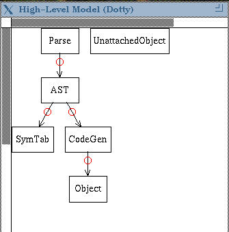
(and may span lines). A source model entity is mapped by the first line in the map it matches (this behaviour can be overridden in the command-line interface to the tools). High-level ModelEach line in a high-level model file either introduces a node or an arc according to the following syntax: Parse AST specifies the following high-level model:
Config (Optional)The graph configuration file describes how to visually display edges in a reflexion model. Each line in the file is of one of the following two formats: node <name> [shape|color]=<value> Lines of the first format specify how various nodes should appear.
The allowable shape and color values are those values supported by
AT&T's graphviz package. Lines of the second format specify how
edges of a particular type should appear. Last Updated: October 20, 2001 Contact murphy@cs.ubc.ca for more information or any problems with this page.
|
