Automated Texture Registration and Stitching
- Similarity Measure for Silhouettes
- Pictures
- SIGGRAPH '00 sketch
- Literature
Similarity Measure for Silhouettes
Since rendering algorithms have become more sophisticated in the last
years also the demand for realistic models has been increased,
especially for models of real world objects. Hereby, not only the 3D
shape but also the surface color or reflectance is of major interest.
The 3D model is commonly obtained by a scanning device producing for
example a triangle mesh. Color information is frequently collected
during a second process using a camera. Generating the entire model
then requires to combine the 3D shape and the 2D images/textures. The
camera position and orientation relative to the 3D mesh must be
computed for each image in order to stitch the textures onto the 3D
surface. In previous work [1,2] the camera settings are determined by
minimizing the error between the outline of the object in the 2D image
and the outline of the projected 3D model.
In contrast to previous algorithms where the error is estimated by a sum
of pixel to outline distances, our approach directly measures the area
enclosed by the two outlines. Since the projection of the 3D model can
be computed using graphics hardware it is very easy and efficient to
obtain this area measurement: as a preprocessing step the 2D image is
segmented into pixels belonging to the background (black) and those
covered by the object (white). For each camera position at first the
3D model is rendered colored white in front of a black background and
the result is combined with the segmented image using a per pixel
XOR-operation. Now, exactly the pixel between the outlines remain
white and their number can be counted by simply evaluating a
histogram.
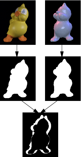
Measuring the difference between the photo and one view of the
model by the area occupied by the XOR-ed foreground pixels.
In addition to the registration based on the silhouette we may further
increase the precision by considering the textures of already
registered views. Hereby, regions of the model where two textures may
overlap are rendered two times, once textured with the already
registered view and once using the texture to be registered. To
measure the current error the difference of both images is computed
per pixel and then summed by evaluating the histogram again.
Since all these steps can be executed in hardware the
non-linear optimization for the camera parameters is significantly
accelerated. Further, the optimization is done hierarchically on
different image resolutions to decrease the rendering effort. Given
the focal length of the camera and a rough estimate for the object
distance it is even possible to obtain the camera position and
rotation without any user interaction in a few minutes.
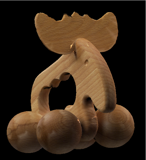
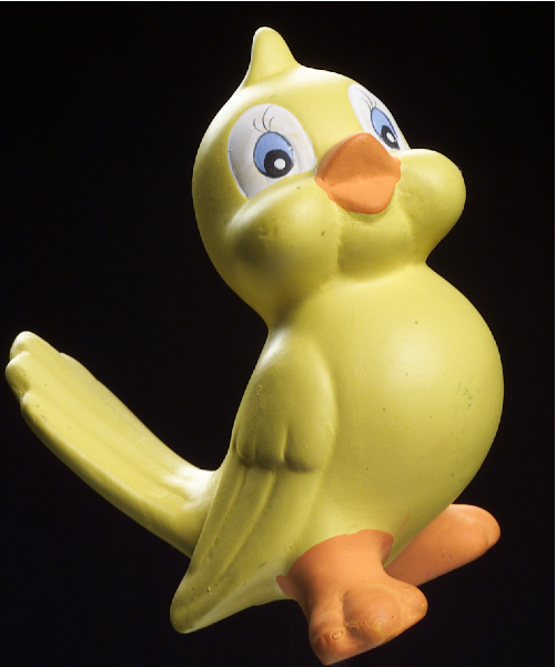
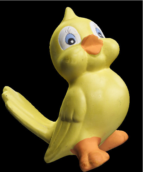
Here some pictures
 |
 |
| photo |
texture |
 |
 |
| photo |
texture |
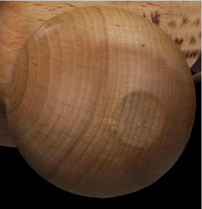
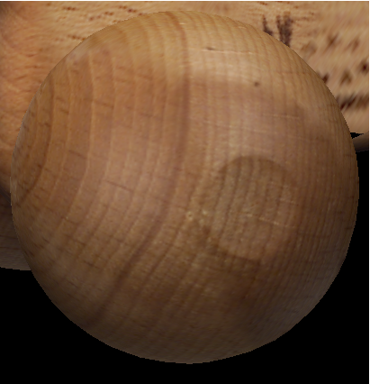
Novel viewpoint. Left column: photo that has not been used to generate the texture. Right column: synthetic model rendered with the generated textures. (Press on any image to run a movie of the textured object.)
Comparing registration results. Due to an inexact 3D model or disturbed silhouettes, the purely silhouette-based registration leads to artifacts in the texture(left). Global optimization using texture comparison resuls in a better alignment of features (right).
SIGGRAPH '00 sketch
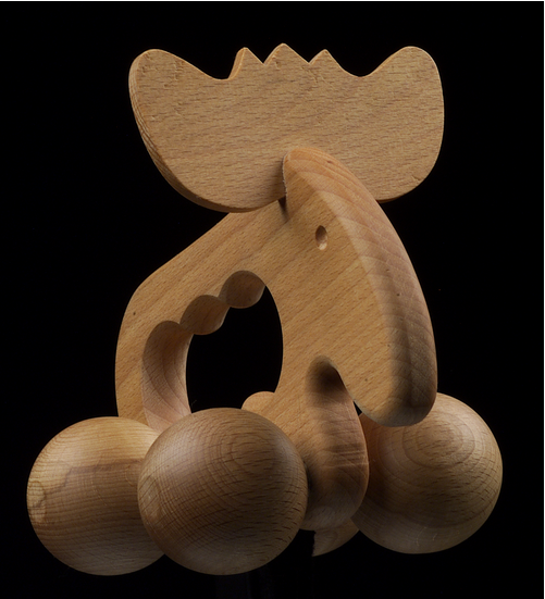
On this project there was presented a sketch at SIGGRAPH '00. You can get the PowerPoint presentation here, which includes three movies: registration using low resolution, registration using high resolution, and a movie of the textured moose.
Literature
Matsushita, K., and Kaneko, T. Efficient and handy texture mapping on 3D surfaces. Computer Graphics Forum 18, 3 (September 1999), 349-358
Neugebauer, P. J., and Klein, K. Texturing 3D models of real world objects from multiple unregistered photographic views. Computer Graphics Forum 18, 3 (September 1999), 245-256
Hendrik P. A. Lensch, Wolfgang Heidrich, and Hans-Peter Seidel.
Automated Texture Registration and Stitching for Real World Models. In Proceedings of Pacific Graphics '00, (accepted for publication).
Errata: In Equation 3 f denotes the effective focal length, not the field of view. They are related by
f = cotangent(FoV/2). In the following text f really denotes the field of view.
Last modified: Fri Jun 8 11:24:24 MDT 2001 by
Hendrik Lensch