Ā
![]()
Ā
In this paper we present observations related to the use of professional tools for the development of real-time systems in undergraduate computer science education, in particular in the development of design skills. We discuss the benefits that can result from the understanding of the design philosophy, concepts, and techniques embodied in an advanced professional toolset. We also discuss the substantial challenges in trying to provide a rich enough context in which the capabilities of tools and diversity of design patterns can be nontrivially illustrated, while keeping the complexity manageable in the classroom environment. In search for resources that can provide sequences of relevant design examples of progressive difficulty and demonstrate incremental system development, we outline a specific relatively complex executable prototype of a real-time system that we have developed using a real-time object-oriented modeling (ROOM) toolset. In terms of its complexity and approach to development, the system prototype is representative of a professional project that can seriously benefit from the use of advanced professional tools. It is rich enough to illustrate a variety of design patterns and tool features. It provides an integral, consistent context for generation of class examples and student projects. It relies on application domain knowledge familiar to everyone, which allows students to easily generate their own semantic variations. The system prototype is dynamically configurable at run time and can be used to derive versions of widely varying complexity. We discuss the expected advantages of the approach and comment on further work towards its integration into the undergraduate computer science curriculum.
Keywords: Real-time systems, computer science education, professional design tools, object-oriented modeling, incremental system development, executable specifications.
![]()
Ā
Ā Understanding tools is an essential part of the learning process in many areas of computing. This is not only because tools empower us by increasing our productivity, but also because they capture the framework of concepts and abstractions that is essential within the scope of their application. A thorough understanding of the purposes and capabilities of a comprehensive specialized professional toolset provides a direct insight into what the specialists typically do at the level of technology that the toolset represents.
In the case of object-oriented design of real-time systems, such a framework of concepts and abstractions has been superbly captured in the Real-time Object-Oriented Modeling (ROOM) methodology [4], which later became the core of the real-time extensions to the Unified Modeling Language (UML) [7, 8]. On their first exposure to this conceptual framework, many designers of real-time systems (ourselves included) have realized that they had been designing similar abstractions for a long time, and that the framework captures significant parts of their professional experience. The line of visual, interactive software tools supporting the ROOM methodology has now been available for about twelve years. Initially represented by ObjecTime Developer™, it became incorporated1 into Rational Rose™ as Rational Rose RealTime™, and more recently became IBM Rational Rose RealTime™. We shall refer to it generically as ROOM tools or RoseRT.
The Real-time Object-Oriented Modeling approach and its associated tools allow the user to develop visual, executable specifications of system structure and behavior. The basic structural blocks are concurrent active classes, called capsules2, that use ports to exchange messages specified by protocols. System structure is represented by hierarchically composed, communicating capsule instances. Capsule behavior is described using a version of Harel's statecharts [2] -- a visual state-machine formalism allowing hierarchical composition. Capsules (like other classes) form inheritance hierarchies. Both structure and behavior can be inherited. Structure, behavior, and inheritance are visually represented and specified through a graphical editor. Visual specifications are automatically translated into higher-level language code (C++ or Java) and can be supplemented by hand-written code. Specifications can be executed and tested in the development environment, and can then be deployed and tested on target hardware. Execution can be viewed through a visual real-time monitor utility that also provides tracing, message injection, and other testing facilities.
There is no doubt that a practicing software professional must be thoroughly familiar with appropriate advanced development tools. However, one might question whether a computer science program that emphasizes broad conceptual education should aspire to systematically develop significant proficiency with specific tools, or should leave such tasks to professional training, and possibly to students' individual initiative within class projects. After all, tools evolve and have limited lifetimes, and students with strong fundamentals should be prepared to master many new development tools (and other software products) throughout their professional careers.
Our point of view is that effective teaching of design concepts and principles requires active involvement of students in the design process at a suitable level of complexity, which can realistically only be done with the support of appropriately complex tools. Otherwise one risks making the examples and assignments manageable through oversimplification, which makes the concepts and techniques look irrelevant to a perceptive student. An early investment in the understanding of tools can be generously repaid later through a proper appreciation of concepts. This approach does not imply a detailed coverage of a full array of tools that a working professional might find useful; a few well-selected, conceptually important tools should suffice. Nevertheless, it is not easy to introduce students to advanced aspects of professional tools; we discuss the pedagogical challenges and some solutions in the next section.
Realizing the educational potential of Real-time Object-Oriented Modeling, we introduced it early on into the undergraduate Computer Science curriculum at the University of Northern British Columbia. Students have had opportunities to work with ROOM tools in course context since mid-nineties. The tools were initially used in undergraduate research and project courses, and later also in distributed systems and software engineering courses. They were also used in faculty research on requirements engineering involving participation of undergraduate research assistants [5].
In this paper we present observations related to our use of ROOM tools
in undergraduate computer science education, in particular in the development
of design skills. A helpful resource for effective teaching of design is a
series of nontrivial examples of progressive difficulty.
The approach we explore in this paper is based on a single design prototype
of a moderately complex real-time system, from which all examples are derived.
We discuss the potential benefits of the approach, outline some characteristics
of a system that we have developed for educational and
research purposes, and discuss how the system can be used to demonstrate
incremental system development using professional tools.
_________________________________________________________________________
1Another tributary to Rational Rose™ was Objectory™, an early object-oriented modeling tool supporting the use case approach of [3]. It was also used at UNBC in 1996/97.
2 Here and elsewhere in this paper, we use the RoseRT version of terminology. The original formulation in [4] uses the term actors, while UML 2.0 [7] uses components.
In this section we formulate a few general observations regarding the use of professional tools for educational purposes, based on our experiences with Real-time Object-Oriented Modeling tools at the University of Northern British Columbia. The tools are intended for professional development of real-time systems, and are particularly powerful in their support for design modeling. They were initially used in undergraduate research (CPSC 495/496) and project (CPSC 490/491) courses, and later in CPSC 441 Distributed Systems, taught by the first author; they have been used regularly in projects on real-time systems within CPSC 300 Software Engineering I and CPSC 301 Software Engineering II, taught by the second author.
Despite the existence of a suitable on-line self-instructional tutorial, reference documentation, help system, and conceptual coverage in [4], some systematic formal teaching is necessary if one wants the students to master the tools beyond the elementary features and simplest techniques. In the process, one needs to expose the students to examples involving characteristic design patterns, which illustrate both the design techniques and proper usage of the tool set. While the same approach may result in a steeper learning curve for experienced professional system designers, for most undergraduate students methodical instruction is a precondition for reaching a solid level of proficiency.
There is a natural tendency to use advanced tools for advanced tasks, such as exploration of various real-time systems issues through senior undergraduate research courses. However, one must be aware that, in order to master advanced tools, a student must first be in a position to apply them to design problems that are thoroughly understood and involve familiar concepts. This became fully apparent in the modeling of tasks involving elements of telecommunication switching systems. While the toolset had been initially developed with that application area in mind and matches its requirements very well, the fact that students were concurrently learning the modeling domain and modeling tools introduced too much uncertainty into the learning process. The progress was much better when the tools were first introduced on design tasks involving simple systems familiar from everyday life, such as coffee machines, coin exchange modules, or juke boxes. The modeling of basic local network interfaces, thoroughly explained in an earlier stage of the course, was also successful.
However, the approach with modeling of simple familiar systems has another limitation. In developing a simple system model, powerful high-level design tools do not offer enough advantage over direct modeling in a familiar programming language, in which the students are already proficient, and the main point of the exercise could be missed. Moreover, the system may not be complex enough to seriously require the design patterns and methods supported by the tools, whose more advanced features may appear artificial and contrived. These are subtle dangers whose effects may not become apparent through the performance of students in class. Like all pedagogical oversimplification, they may have longer-term, less conspicuous alienating effects upon stronger students who expect to be properly motivated and fully convinced.
Given a sufficiently complex project, one could try to guide the class through a series of design subtasks of increasing complexity and help them discover the appropriate design patterns and corresponding tool features. Where the prerequisite design experience and intuition exist, discovery is certainly the best way of learning. Where prior experience is insufficient, which is often the case in undergraduate teaching, existing examples that provide some room for variation are a valuable teaching resource. Preferably, such examples should belong to an application domain that is familiar to everyone. It is also helpful if the examples are related and introduce design complexity incrementally, so that a new moderately complex task includes already familiar subtasks. The approach explored in this paper is to select a type of system whose functionality is familiar from everyday life, build a sufficiently complex, modular prototype that illustrates both elementary and advanced capabilities of the toolset, and present its design in an incremental manner, asking the students to vary and expand some aspects of design models.
The use of abstraction in incremental, stepwise development of design solutions has long been recognized as the only effective approach to mastering complexity. Starting with early observations on the nature of programming by Dijkstra, Hoare, Wirth [1], Parnas, and others, this approach has led to major advances in language design, creation of powerful high-level design tools, and software engineering methodologies. Advanced object-oriented modeling tools, intended for professional system development, can provide excellent educational resources for understanding the power of well-chosen abstractions and the nature of incremental development. In the context of our approach, the relatively complex system model that we use as a basis must provide a path of incremental development that can be followed in the educational process.
Not having found a suitable design prototype in the literature, we have developed one that serves as a source of nontrivial examples for teaching and research purposes. Its systematic presentation is beyond the size and scope of this paper. In order to illustrate its level of complexity, some capabilities of the toolset, and the design approach, we first outline elements of its global software architecture, and then provide examples of structural and behavioral design specifications.
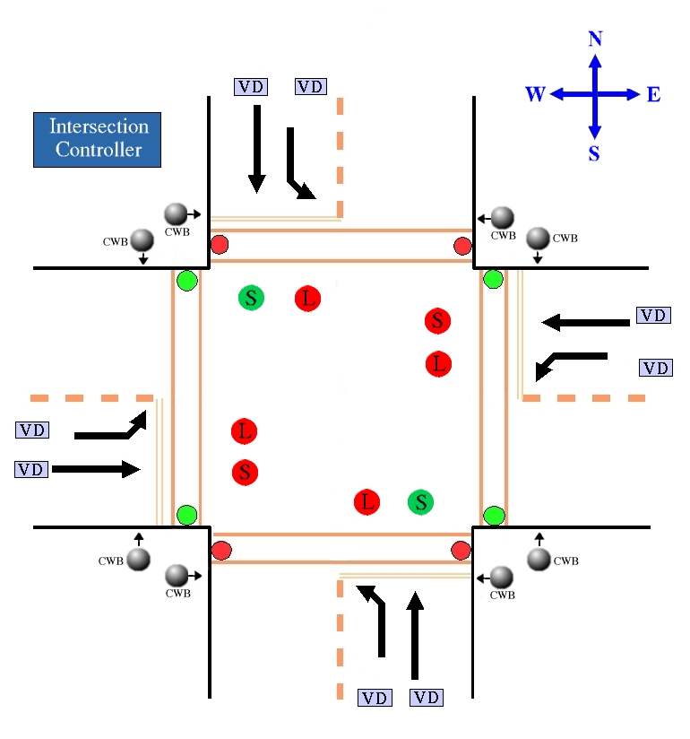
In order to meet the requirements described in the previous section, we undertook the development of a reasonably complex executable model of a real-time system with familiar functionality. The project, called Traffic Intersection Signaling Control System (TISCS), models a rather general intersection of X or T type, which may include turning lanes and pedestrian crossings, vehicle sensors and pedestrian crosswalk buttons. It also permits daily schedules consisting of different signal plans, as well as periodic or aperiodic activation of such schedules based on a longer term calendar.
The most general type of intersection that can be modeled in TISCS is shown in Fig. 1. We refer to the two intersecting streets as directions A and B. For simplicity, we assume that the signaling on each street is symmetric; for instance, on a north-south street, northbound traffic always faces the same signals as southbound traffic. Within each direction (i.e., street), we distinguish three paths: straight (S), left (L), and pedestrian (P). Each path has traffic lights and sensors on each side. The sensors on vehicle paths (S and L) are vehicle detectors marked VD in the diagram. The pedestrian sensors are crosswalk buttons, marked CWB. The signaling is governed by the Intersection Controller (IC), shown in the upper left corner.
The TISCS prototype was developed in RoseRT, which means that it can be executed, monitored and tested during execution, and in principle could be deployed into a target hardware environment. Thus it could be adapted to function as a real traffic control system. Its document set has been developed following the IBM Rational Unified Process (RUP)™3 [6]. Since the completion of its current version in 2002, it has been used by the second author in teaching Software Engineering I and II, and by the first author for the introductory lecture on tools in a research project course on object-oriented modeling of real-time systems.
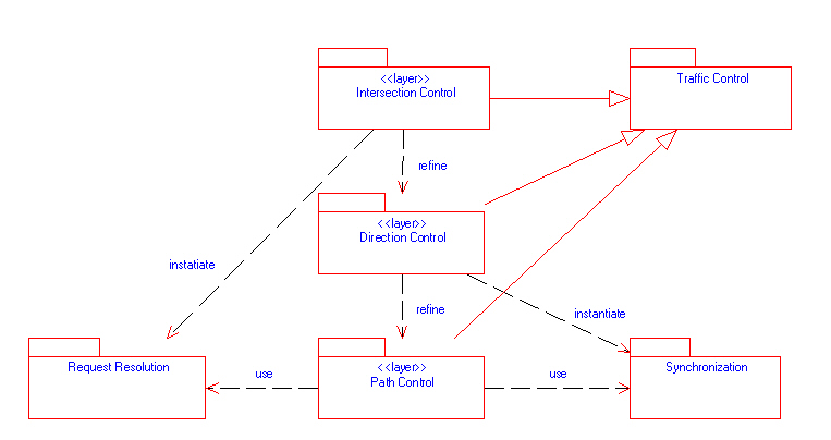
The actual signaling control is largely concentrated in the Path Control layer, within the Signal Controller capsules introduced later on. At that level, there are two coordination issues between paths. The first one is synchronization in the sense of deciding which path has the right to go green and ensuring that all the paths that conflict with it remain red. The necessary capsules and protocols are grouped in the Synchronization package. The second issue is request resolution in the sense of ensuring that all sensor requests are properly routed to all the paths whose signaling they may affect. This functionality is supported by the Request Resolution package. The dependencies in Fig. 3 also show that the Intersection Control layer instantiates the capsules used in request resolution and that the Direction Control layer instantiates the capsules used for synchronization.
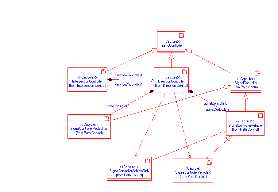
The central components of control layers are the corresponding controller capsules: Intersection Controller, Direction Controller, and Signal Controller. They are all derived from a common abstract ancestor called Traffic Controller, as represented by inheritance arrows (with triangular heads) in Figure 4. Furthermore, Signal Controller is also an abstract capsule from which we derive Signal Controller Pedestrian and Signal Controller Vehicle. The latter has two descendants: Signal Controller Vehicle X, used for the straight path that must be coordinated with a parallel pedestrian path equipped with crosswalk buttons, and Signal Controller Vehicle Only, used for all other vehicle paths.
3The work on the RUP model of TISCS was supported by the Rational Software Corp.,
presently within International Business Machines (IBM) Corp.
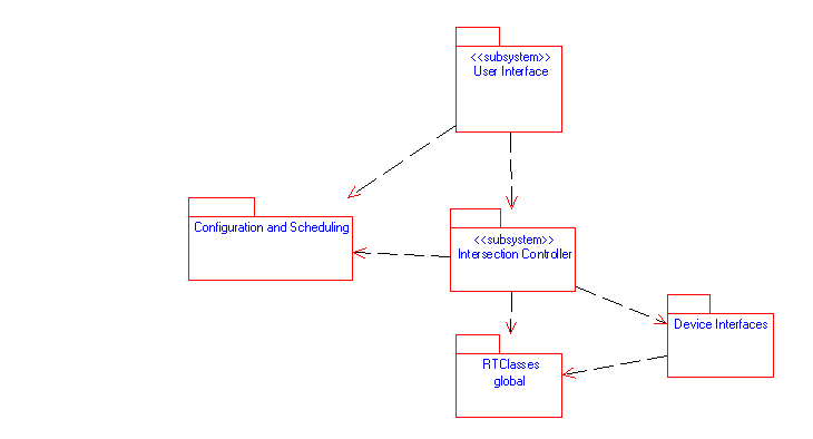
We now examine the containment hierarchy of controller capsules, starting with the structure diagram of Intersection Controller in Fig. 5. The Intersection Controller capsule is externally controlled through its maintenance port of type Maintenance IC. It also has twelve ports for communication with device interfaces. These include six ports of type Signal Lights for communication with the signal lights interfaces for each path, and six ports of type Sensors for communication with the sensor device interfaces for each path. The protocols Signal Lights and Sensors are defined within the Device Interfaces package, shown in Fig. 2.
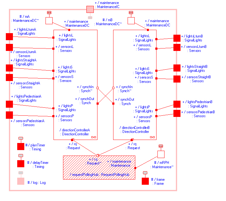
Each direction controller has its own external ports for the lights and sensors interfaces on its three paths. Those direction controller ports are directly connected to the corresponding ports of the Intersection Controller capsule. The device interface ports of Intersection Controller are therefore classified as relay ports -- they merely transfer messages between the external environment (device interfaces) and the internal capsules (direction controllers) without any interference by the Intersection Controller behavior. A relay port is always of the same type as the port to which it connects (it is not conjugated), which reflects its role of a proxy rather than partner in the communication.
Intersection Controller also contains an optional (represented as dashed) capsule role called request Polling Hub, whose purpose is to help route the sensor requests. Obviously, it can be needed only if the intersection configuration actually includes sensors. When Intersection Controller receives a message to configure itself, its behavior checks whether any sensors are present in the intersection configuration supplied in the message. If the configuration includes sensors, the Intersection Controller behavior dynamically incarnates the role with an instance of the Request Polling Hub capsule. Once the instance has been created, Intersection Controller can communicate with it through its internal port mRPH. The Request Polling Hub capsule and its Request protocol belong to the Request Resolution package. The principle that optional capsule roles are dynamically incarnated as needed is followed throughout the design of the Intersection Controller subsystem.
The remaining four internal ports of Intersection Controller are its service access points to the Real-Time Classes package, incorporated from the toolset as a part of the RoseRT virtual machine. Two of the ports provide access to the Timing service (for measuring time intervals), one to the Log service (for logging messages to system operators through standard output), and one to the Frame service (for dynamic incarnation of capsule roles). The Communication service is accessed implicitly through the implementation of port communications. Note the difference in color between the Log port, which is inherited from Traffic Controller, and the others that are defined at the Intersection Controller level.
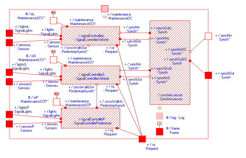
The Direction Controller capsule is similarly decomposed into subcapsules, as shown in Fig. 6. Its main elements are the three SignalController capsule roles, one for each path. When Direction Controller receives a message to configure itself, it checks which paths are present in the supplied configuration and dynamically incarnates the corresponding roles. Two of the roles, signal Controller S and signal Controller L, are of type Signal Controller Vehicle, while the third, signal Controller P, is of the type Signal Controller Pedestrian. When the system is being reconfigured or shut down, it destroys the dynamically incarnated instances.
In incarnating the signal controller roles for vehicle paths, Direction Controller must also take into account whether the pedestrian path is present. If it is, then signal Controller S will have to coordinate with signal Controller P and must be incarnated as an instance of Signal Controller Vehicle X, which is the derived capsule of Signal Controller Vehicle for the case when the pedestrian crosswalk signaling is present. If it is not, then signal Controller S is incarnated as an instance of Signal Controller Vehicle Only, which is another descendant capsule of Signal Controller Vehicle. The L path never involves pedestrian coordination. Consequently, whenever the L path exists, signal Controller L is incarnated as an instance of Signal Controller Vehicle Only.
The Direction Controller capsule also contains an auxiliary capsule role, synch Accessor. Its type Synch Accessor belongs to the Synchronization package, and we shift our focus temporarily from control to synchronization issues. synch Accessor is connected to the Synch ports of all vehicle signal controller roles within the direction and, through the Synch relay ports on the direction controllers, to the synch Accessor within the other direction. The purpose is to connect all the incarnated vehicle signal controllers within both directions into a logical ring. The goGreen message of the Synch protocol, which indicates that the sender has switched its signal lights to red and is authorizing the recipient to switch its signal lights to green, is then propagated like a timed token around the ring. This provides a low-level mutual exclusion mechanism that is resilient to failure of any TISCS elements other than signal controllers or synchronization accessors. Given the critical importance of mutual exclusion of green lights on conflicting paths, this design feature enhances the overall safety of the system.
The synch Accessor capsule role is dynamically incarnated like the other capsule roles, but for different reasons. It is not optional and must always be incarnated. However, the connections it must establish depend on which vehicle signal controllers have been incarnated. Assuming that the S path (for straight vehicle traffic) is always present, and that the L path (for left turns) is optional, we derive from the Synch Accessor capsule the versions Synch Accessor S (for straight-only) and Synch Accessor SL (for straight-and-left). Depending on whether the L path is present in the direction configuration, Direction Controller will incarnate synch Accessor with an instance of the correct derived capsule.
The fragment that we have just described is an instance of a more general design pattern. An accessor is a capsule stereotype that serves as an interconnection network for other components. It has no behavior and simply relays messages through its internal connections. When we want those connections to be dynamically configurable, we can design a generic accessor capsule from which we derive subcapsules with specific interconnections. Our general design then makes use of the generic accessor role, which for each specific configuration gets dynamically incarnated with an instance of the proper subcapsule type.
The behavior of a generalized controller (i.e., of the abstract TrafficController capsule) is shown in Fig. 7. It is expressed in the form of state machine diagram employed by the ROOM methodology (and often referred to as the ROOM-chart). Transitions between states are triggered by external events such as timeouts or arrivals of messages at ports. Transitions can have actions attached to them (symbolized by full arrowheads), and states can have entry actions and exit actions (the icon in state Failed in the diagram symbolizes an entry action). The actions are expressed in programming language code (usually C++). States can be composite and expand into state diagrams (the icon in state Operating indicates this).
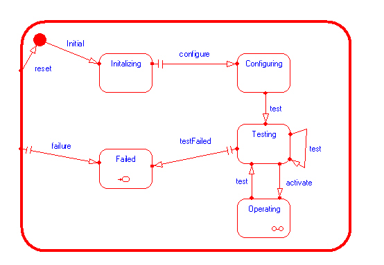
The diagram shows that at startup the controller first performs the initialization (state Initializing), then the message configure triggers the transition into the Configuring state. Next, the arrival of a test command triggers the transition to Testing, which can be repeated a number of times. In the Testing state, test commands are passed on to the elements of the controller, and a response testFailed from any of them triggers the transition to Failed. If the testing was successful, the controller is ready to receive the activate command and transfer to Operating, a composite state where it performs its signaling activities. Regardless of which state the controller is in, a reset message will cause it to reinitialize, and a failure message from any of its elements will transfer it into Failed. The details of transition triggers and actions are mostly left unspecified at this level of abstraction, and supplied for each of the more concrete controller capsules. A broken arrow indicates that no trigger has been specified, and an empty arrowhead indicates that no action has been associated with the transition.
In order to consider a different fragment of behavior design, we now descend through the inheritance hierarchy from Traffic Controller to the (still abstract) Signal Controller, which controls the path signaling in its Operating state. This is a composite state with multiple levels of decomposition. At the first level, it contains External Control, where the intersection signaling is manually controlled, and Internal Control, where it is controlled by timer signals based on a signal plan. Internal Control is further decomposed into Loading Plan, where a new signal plan is installed, and Normal, which drives the regular green-yellow-red light cycle. The internal behavior of Normal is shown in Fig. 8.We mentioned earlier that signal controllers on different paths pass the exclusive right to turn green to each other through a token-based peer protocol. This is represented by the start Green transition in the diagram, which is always triggered by a message from another controller. The duration of Yellow is always controlled by cycle Timer, implemented through an interval timing service from the RoseRT virtual machine. The transition from Green to Yellow can in various situations be triggered by cycle Timer, by a go Yellow message from another signal controller, or by a request Poll Success message from request Polling Hub, indicating a sensor activation that requires the transition. However, when a new plan is installed, the peer symmetry must initially be broken; one controller is told from above to go green (through the start New Plan transition into Normal state), while others are told to go red (through the passive Start transition in the diagram).

The Normal state has self-transitions, in which external events trigger actions but the state remains the same. There are four self-transitions -- one triggered by a sensor activation, the others by sensor request resolution events. The full arrowheads indicate that there are actions associated with these transitions. At the moment of transition, the control may actually be in a substate of a composite state. Substates, and the state itself, may have entry actions, and the finer points of semantics regulate which states are re-entered, with entry actions re-executed, during a self-transition. The H (for `history') symbol in the diagram is related to such semantic distinctions.
The Signal Controller capsule, to whose behavioral specification the Normal state belongs, is abstract and thus never instantiated. It is used to derive concrete capsules such as Signal Controller Pedestrian or Signal Controller Vehicle X. The concrete capsules will inherit the behavior from its ancestors, such as the transitions in Fig. 8, and additionally specify their own behavior. Even where the transition actions are specified in an ancestor, as in the case of self-transitions, the derived class can add its own actions.
We have argued earlier, in Section 2, that professional design tools can be valuable teaching resources, provided that one has a base of realistic design examples, and adopts an incremental approach that makes the complexity manageable. We can now revisit those two conditions with a view to the TISCS prototype discussed in Sections 3, 4, and 5.
In its level of complexity and design approach, TISCS resembles a professional project in which significant advantages can be derived from the use of advanced professional tools. Its overall development has followed an established software process (IBM RUP), although with fewer artifacts than a professional project would typically have. Its functionality is fairly complete and addresses a variety of practical requirements. These characteristics clearly distinguish TISCS from a multitude of popular class projects inspired by traffic control.
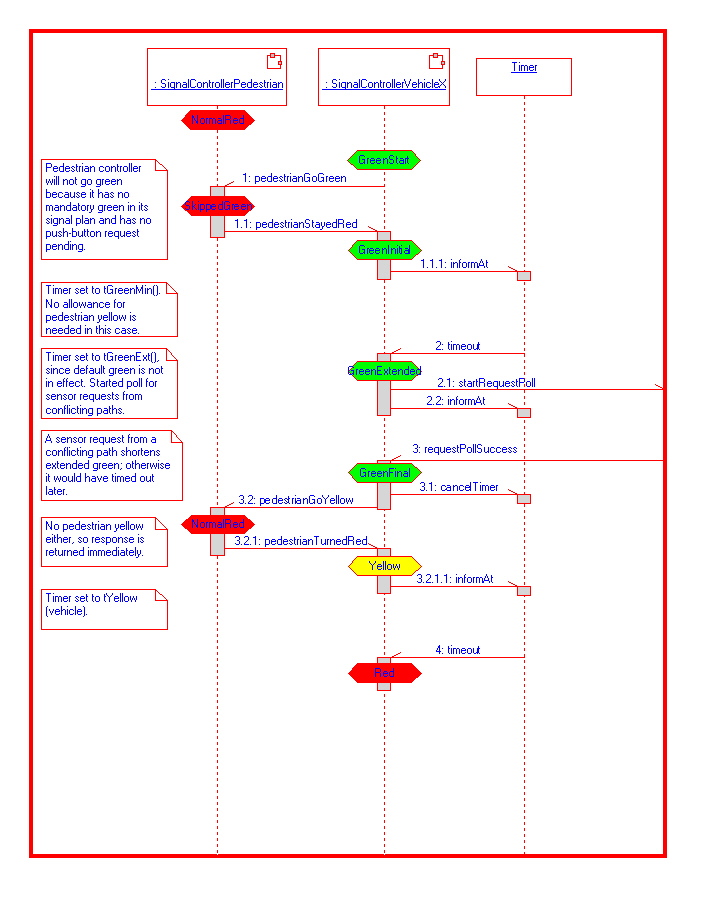
The system belongs to an application area that is familiar to everyone, and yet involves relatively complex synchronization and coordination tasks. For instance, the sequence diagram of Fig. 9 illustrates the interactions between two signal controllers belonging to the same traffic direction -- one controlling vehicles going straight, the other pedestrians walking on a parallel path, in the presence of vehicle detectors and crosswalk buttons. The use of the sequence chart is fully justified by the complexity of the interactions. Yet the motivation for the particular approach to controller synchronization is not difficult to explain, nor is it hard for a student to think of semantic variations of sensor request resolution that would make sense in the context of realistic intersection control.
The model is rich enough to illustrate a variety of design patterns and tool features. For instance, the family tree of traffic controllers in Fig. 4 provides a wide variety of inheritance relationships with respect to structure and behavior. The fact that the examples belong not only to a single application area but to a single functioning system also leads to some advantages. The system provides a wider design context in which one can evaluate every individual design element. The questions on how an element relates to a large picture can be answered in a definitive way, not speculatively as in isolated class examples. An interested student can proceed to examine the relationship in detail, including the monitoring of execution and initiating specific execution scenarios with message injections at capsule ports.
The model is also complex enough to illustrate the critical importance of disciplined, methodical design. For instance, one can reflect on how complex would be the design of the collection of various traffic controllers of Fig. 4, had we not carefully abstracted the common properties and used inheritance to add variation to the common basic capsule design. While one can gain a conceptual understanding of inheritance from much simpler examples, and use imagination to extrapolate the benefits to larger models, a realistic sense of its practical significance can only result from exposure to realistic examples. Models and patterns that can demonstrate the capabilities of professional tools without trivialization are more readily found in projects that resemble professional work than in typical lecture illustrations.
An essential aspect of TISCS that makes it suitable for demonstrating incremental design is the dynamic configurability of its structure. By changing configuration descriptions given to the Intersection Controller as a part of the configuration message, one can create prototypes of varying complexity. For instance, a simple X intersection with no left-turn signals, no pedestrian traffic lights, and no sensors, is at least an order of magnitude simpler than the full model. Such versions can easily be generated, executed, monitored, tested, and fully understood. After that, a student has a reasonably complex familiar context in which various design patterns and tool features can be exercised through modifications of the existing model, or through its redesign at a less general level.
We should point out that in spite of our substantial experience with the classroom use of ROOM tools, and some classroom experience in the use of TISCS, the approach explored in this article has not yet been systematically tested. For this, additional work is needed in the development of a specific sequence of classroom examples and its incorporation into class tutorials. The likely testing ground for this is the two-course sequence Software Engineering I and II, where the first course largely includes theoretical background, some exposure to tools, and the requirements engineering part of the project (including initial prototyping), while the second course is fully project-oriented and focuses on the design and implementation stages. The current experiences with the classroom use of TISCS are mainly derived from those courses. We expect that a full implementation of the approach is possible in the context of a software engineering stream, with gradual introduction to tools through a sequence of several courses.
Ā
In this article we have described our observations on possible use of professional tools for real-time system development in the context of undergraduate computer science education. We have pointed out that advantages involve not only the practical skills relevant to the professional workplace, but also conceptual understanding and realistic appreciation of the design techniques and methods embodied in the toolset. We identified a number of difficulties in using relatively complex tools within the limitations of class projects, and reported some specific experiences. The basic conclusion was that professional design tools can be highly valuable, provided that one has a base of realistic design examples, and adopts an incremental approach that makes the complexity manageable. We then outlined a specific system model that we had developed to meet the identified criteria.
In terms of its complexity and approach to development, the model is representative of a professional project that can seriously benefit from the use of advanced professional tools. It is rich enough to illustrate a variety of design patterns and tool features. It provides an integral, consistent context for generation of class examples and student projects. It relies on application domain knowledge familiar to everyone, which allows students to easily generate their own semantic variations. The model is also complex enough to illustrate the critical importance of disciplined, methodical design. The model is dynamically configurable at run time and supports a wide range of configurations of varying complexity. This property facilitates the generation of examples of progressive difficulty, which can serve as bases for student variations and redesigns.
On the whole, the model's properties recommend it as a suitable educational resource in demonstrating incremental development with professional tools. While its development has been motivated by specific experiences of the authors, the approach requires further work leading to its integration into course curricula. In particular, it seems appropriate for a software engineering stream, where student proficiency with specific tools can be gradually developed through a sequence of several courses.
Ā
Ā
![]()
| Name | Jernej Polajnar | Desanka Polajnar |
| Department | Computer Science | Computer Science |
| Institution | University of Northern British Columbia | University of Northern British Columbia |
| Postal address | 3333 University Way | 3333 University Way |
| Prince George, B. C. | Prince George, B. C. | |
| Canada, V2N 4Z9 | Canada, V2N 4Z9 | |
| E-mail address | polajnar@unbc.ca | desa@unbc.ca |