|
|
Synchronization and Rolling Shutter Compensation for Consumer Video Camera ArraysDerek Bradley, Bradley Atcheson, Ivo Ihrke, Wolfgang Heidrich |
IEEE International Workshop on Projector-Camera Systems (PROCAMS 2009)
2nd Best Paper Award!
Download: PDF
Bibtex:
@INPROCEEDINGS{Bradley:2009,
author = {Derek Bradley and Bradley Atcheson and Ivo Ihrke and Wolfgang Heidrich},
title = {Synchronization and Rolling Shutter Compensation for Consumer Video Camera Arrays},
journal = {International Workshop on Projector-Camera Systems (PROCAMS 2009)},
year = {2009},
}
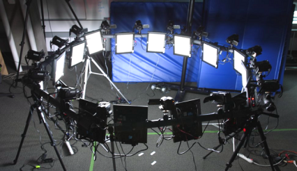
AbstractTwo major obstacles to the use of consumer camcorders in computer vision applications are the lack of synchronization hardware, and the use of a "rolling" shutter, which introduces a temporal shear in the video volume. We present two simple approaches for solving both the rolling shutter shear and the synchronization problem at the same time. The first approach is based on strobe illumination, while the second employs a subframe warp along optical flow vectors. In our experiments we have used the proposed methods to effectively remove temporal shear, and synchronize up to 16 consumer-grade camcorders in multiple geometric configurations. |
|
Rolling Shutter Camera Model
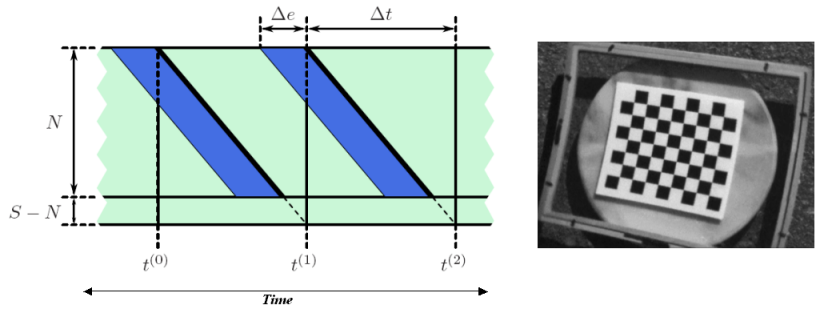
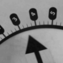
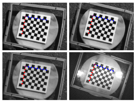
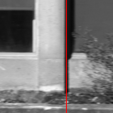
In the rolling shutter camera model, just-in-time exposure and readout of the individual scanlines creates a shear of the exposure intervals along the time axis. The slope of this shear is a function of the camera frame rate and the period is determined by the number of scanlines in the video format. A fast rotating checkerboard captured with a rolling shutter camera has straight lines that are warped into curves.
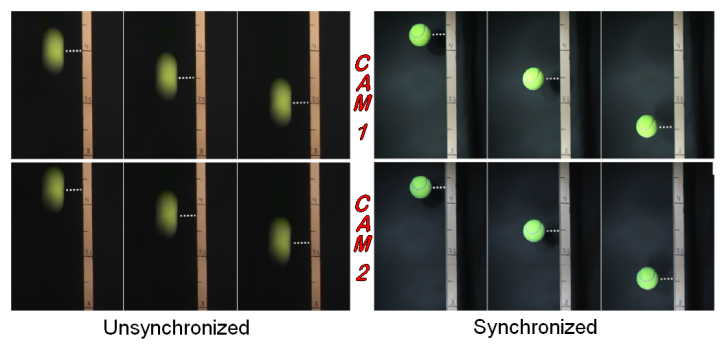
Method 1: Stroboscope Illumination
Stroboscopes create instantaneous illumination for all scanlines of all cameras.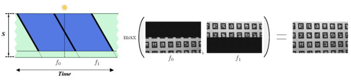
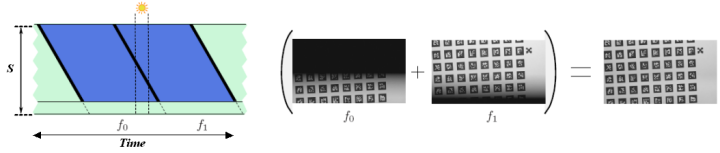
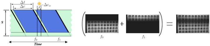
Method 2: Subframe Warping
Our subframe warping method removes the rolling shutter distortion and synchronizes multiple cameras by interpolating intermediate frames. We compute optical flow between adjacent frames, and then perform the interpolation using different offsets for each scanline.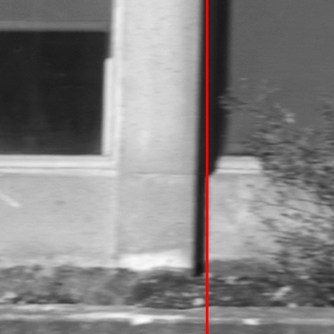
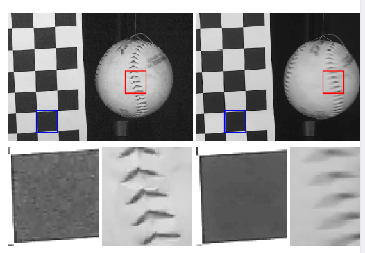
Experiments